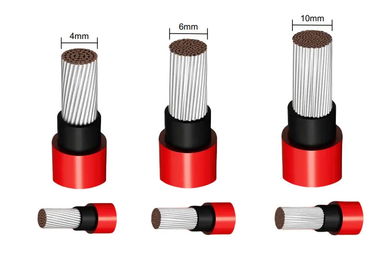
Maximizing Solar Efficiency: A Practical Guide to PV Cable Run Length, Power Loss, and Wire Gauge
When designing or upgrading a solar installation, one seemingly minor detail can have a huge impact on overall performance and ROI: the cables that connect your panels to the rest of the system. Below, we’ll break down why cable run length and wire gauge (AWG) matter, how they affect voltage drop (and thus energy losses), and what steps you can take to optimize your setup. If you want in-depth voltage-drop figures at various currents and distances, be sure to check out our “cheat sheets” for 12 AWG, 10 AWG, and 8 AWG PV wires.
Why Cable Run Length & Voltage Drop Matter
1. Energy Efficiency
Every foot of wire introduces resistance—causing a phenomenon called voltage drop. If your panels produce 12 V and you lose 1–2 V in transit, that’s a significant percentage of your total. Larger drops mean less power reaching your inverter or batteries, lowering overall system efficiency.
2. Project Profitability
Solar ROI depends on how much electricity you can reliably generate. Voltage drop leads to wasted energy; over time, those losses eat into profits. Especially in commercial or high-capacity residential systems, a small percentage can translate to thousands of kilowatt-hours lost.
3. Equipment Reliability
Severe voltage drops can cause inverters or charge controllers to run outside ideal parameters, triggering faults or shutting down prematurely. Keeping losses in check ensures stable operation—and fewer support calls.
Key Factors Influencing Power Loss
-
Current (Amps)
- Higher currents amplify the effect of any given wire’s resistance. Doubling the current roughly doubles the voltage drop.
-
Distance (Feet or Meters)
- The longer the run, the more chances for voltage loss. Doubling the distance also roughly doubles the drop.
-
Wire Gauge (AWG)
- Thicker wire (a lower AWG number) has less resistance but costs more. Thinner wire (higher AWG) is cheaper but risks excessive losses or code violations.
-
Conductor Material & Quality
- Most PV systems use copper wire due to its superior conductivity. Ensure it meets relevant UL or IEC standards for reliability.
-
Temperature & Installation Environment
- Heat reduces a wire’s ampacity. If your cables are bunched together in a conduit under a scorching roof, you may need thicker wire to handle the load safely.
Choosing the Right Wire Gauge: Striking the Balance
1. Aim for Low Voltage Drop
Many solar designers target 2–3% maximum voltage drop, though mission-critical or off-grid applications may aim closer to 1–2%.
2. Check Ampacity & Code Requirements
Don’t size based on voltage drop alone—you must meet NEC (National Electrical Code) or local equivalents, which include rules on overcurrent protection, conduit fill, and grounding.
3. Consider Higher System Voltage
Switching from 110V to 240 V or higher cuts current for the same power, naturally reducing losses.
4. Shorten Your Runs
Whenever possible, place inverters and charge controllers closer to your array or battery bank. Less distance, less drop!
Using Our Three “Cheat Sheets”
We’ve compiled three reference guides packed with voltage-drop tables for 12 AWG, 10 AWG, and 8 AWG solar cable:
-
12 AWG Cheat Sheet
- Excellent for smaller residential or off-grid setups.
- Quickly highlights how rising current or distance can push drop percentages skyward at lower voltages like 12 V or 24 V.
-
10 AWG Cheat Sheet
- A step up in ampacity and lower resistance.
- Ideal for medium-sized systems where 12 AWG just isn’t cutting it, but you want to avoid the material cost of 8 AWG.
-
8 AWG Cheat Sheet
- Lower resistance yet, perfect for larger or higher-current projects (e.g., 30 A to 50 A circuits) or moderately long distances.
- Especially useful for many commercial installs or big residential arrays where 10 AWG might still cause too much drop.
Each cheat sheet shows how voltage drop scales at different currents (5 A–50 A) and one-way distances (6 ft–400 ft), with columns for voltages up to 1500 V. Whenever voltage drop tops 100% of the circuit voltage (impossible to operate effectively), we label the cell “>99%.”
Practical Tips to Lower Power Loss
-
Raise System Voltage
- Jumping from 24 V to 48 V (or beyond) can significantly cut current, slashing voltage drop across the same gauge.
-
Go Thicker
- If your target drop is 2% but 12 AWG yields 4–5%, upgrading to 10 AWG or 8 AWG could save energy (and potentially pay for itself over time).
-
Optimize Layout
- Combine parallel module strings at a combiner box near the array, then run a single (thicker) home run to the inverter.
-
Regular Maintenance
- Loose or corroded connections increase resistance. Periodic checks ensure your system remains at peak efficiency.
Final Thoughts
Cable run length and wire gauge selection aren’t just technical footnotes—they’re pivotal to a well-performing, long-lasting solar system. By keeping voltage drop within recommended limits, you’ll enhance energy harvest, safeguard your equipment’s reliability, and boost overall return on investment.
Ready for more specific numbers? Check out our dedicated “cheat sheets” for 12 AWG, 10 AWG, and 8 AWG solar cables to see how different distances, currents, and voltages stack up. With a data-driven approach, you can pick the right conductor for your project—optimizing cost, compliance, and power output.


